Injection moulding is an industrial process in which a thermoplastic polymer is melted and injected at high pressure into a closed mould shaped like the component. The material fills the cavity, is held under pressure as it cools and solidifies, then is ejected; the mould closes again and the cycle repeats identically, even hundreds of times an hour. It is the most widespread technique for mass-producing plastic components with consistent quality and low unit cost.
Injection moulding, explained by the people who do it
Injection moulding is the technique that produces most of the plastic objects you use every day, from car components to electronics housings to caps and toys. It is so widespread because, once the mould is ready, it turns out the same part thousands of times with repeatable dimensions and at a cost per part that falls as volumes rise.
On this page we explain how the process really works: the stages of the cycle, the parameters that count, the materials and the typical defects. We do so from a slightly unusual standpoint. At FPM we don’t just talk about injection moulding, we have practised it for over 40 years, and before that we build the mould the parts come out of. When a defect originates in the tooling and not in the press, we notice it immediately, because we have our hands on both.
What injection moulding is
Injection moulding is a manufacturing process in which a thermoplastic polymer is melted and injected at high pressure into a mould shaped like the desired component. The material fills the cavity, cools and solidifies taking that shape, then is ejected as a finished part. At that point the cycle starts again, identical, dozens or hundreds of times an hour.
The idea is simple, but the result depends on many details: the shape and number of cavities, the point where the material enters, the way the mould dissipates the heat and the parameters the press works with. It is the combination of these choices that separates a compliant part from one full of defects. This is why injection moulding is a precision technique, not a simple pour: the mould and its fine-tuning matter as much as the machine.
The raw material arrives in granules, often already coloured or with additives. Almost exclusively thermoplastic plastics are worked, those that soften with heat and resolidify on cooling, a cycle that can be repeated. Thermosets and elastomers have their own processes.
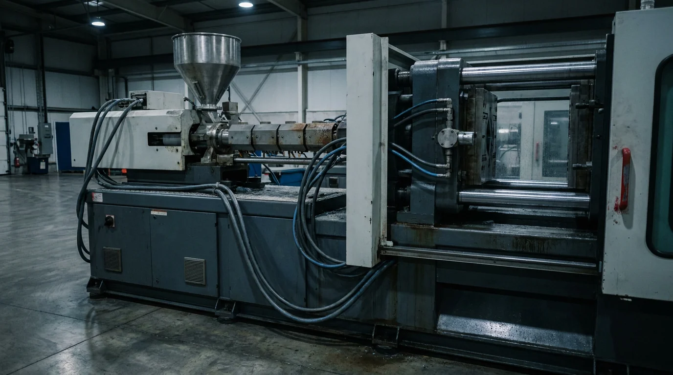
How the injection moulding machine works
Everything happens on an injection moulding machine, a machine made up of two units that work in sequence.
The injection unit melts and meters the material. The granules drop from a hopper into a heated barrel, inside which a screw turns. The screw draws the material forward and, between mechanical friction and the heat of the bands, brings it to a molten state; when it has accumulated enough, it stops turning and moves forward like a piston, pushing the melt into the mould.
The clamping unit holds the two mould halves closed while the material enters under pressure. The key parameter here is the clamping force, in tonnes: it must overcome the thrust the melt exerts on the cavity walls, otherwise the mould opens and flash appears. A rough shop-floor rule of thumb allows around 2-5 tonnes per square centimetre of projected area. Presses range from a few dozen tonnes up to over 1,000 for large parts.
They differ in how they move the units: hydraulic (robust, for high pressures and large parts), electric (precise and efficient, higher initial cost) and hybrid, which combine the two approaches.
The 4 stages of the injection moulding cycle
The cycle always repeats the same way, stage after stage. Knowing them helps to understand where defects arise and where time is recovered.
01 Plasticising (dosing)
While the previous part cools, the screw turns, draws the granules forward and brings them to a molten state with friction and the barrel’s heater bands. The melt accumulates in front of the screw tip, which meanwhile retracts: this is the shot ready for the next moulding. A slight back pressure helps homogenise the mass and drive out the air.
02 Injection (filling)
With the mould closed, the screw moves forward like a piston and pushes the melt into the cavity at high speed. Depending on the material and geometry, the injection pressure can range from about 500 to over 2,000 bar. When the cavity is almost full, around 95-98%, the machine switches from the filling phase to the holding phase.
03 Holding and cooling
A holding pressure, lower than the injection pressure, keeps pushing material into the cavity to compensate for shrinkage as the part solidifies, so the dimensions stay stable and sink marks are avoided. The heat is removed by the temperature-control channels, usually water-fed, machined inside the mould. It is the longest phase: on many parts it accounts for more than half the cycle time.
04 Ejection
Once the part has solidified the mould opens and the ejectors, sometimes helped by a robot, release the component. The mould closes again and the cycle restarts from plasticising.
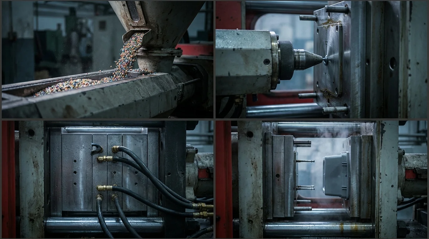
A full cycle usually lasts between about 15 and 60 seconds, faster for thin parts and longer for thick ones, where cooling dominates. Cutting even a couple of seconds off the cycle, over a long production run, means thousands more parts by the end of the year: this is why fine-tuning the cooling matters so much.
The parameters that make the difference
Behind a well-moulded part there is a balance of parameters kept under control. Changing one shifts the others, which is why fine-tuning is a craft and not a fixed recipe.
- Melt temperature. It decides how well the polymer flows. Too low, and the material does not fill; too high, and it degrades. Every material has its own window.
- Mould temperature. It affects cooling, surface finish, shrinkage and internal stresses. Engineering polymers need a hot mould, even over 100 degrees.
- Injection pressure and speed. They govern how and how quickly the cavity fills. The wrong speed leaves streaks, jetting or flow lines.
- Holding pressure and time. They compensate for shrinkage in the solidification phase. They are the first remedy against sink marks.
- Cooling time. Often the longest part of the cycle: it determines how many parts you produce in an hour and how stable they are dimensionally.
- Back pressure and screw speed. They control the homogeneity of the melt during dosing.
Finding the right combination is the work of fine-tuning, and it is what separates a consistent production run from one full of scrap. The values change with every material, every geometry and every mould: the experience built up on many different parts is what shortens this phase.
Which materials are injection moulded
Almost the entire thermoplastic family is injection moulded, from the most common ones to high-performance engineering polymers, including glass-fibre filled grades for the most demanding applications. Every polymer has a temperature window within which the melt must be brought and a shrinkage with which it contracts as it solidifies, on which the dimensions to be cut into the mould depend. Some materials, called hygroscopic (polyamide, polycarbonate, ABS, PBT, PET), absorb moisture and must be dried before moulding, otherwise the water in the granules causes bubbles and streaks.
| Material | Code | Structure | Melt temperature | Shrinkage | Typical uses |
|---|---|---|---|---|---|
Polypropylene | PP | semi-crystalline | 200-260 °C | 1.2-2.5% | containers, car parts, household goods |
Polyethylene | PE (HDPE) | semi-crystalline | 180-260 °C | 1.5-3.0% | caps, bottles, packaging |
ABS | ABS | amorphous | 210-260 °C | 0.4-0.8% | housings, cosmetic parts |
Polystyrene | PS | amorphous | 180-260 °C | 0.4-0.7% | technical items, packaging |
Polycarbonate | PC | amorphous | 280-320 °C | 0.6-0.8% | transparent and technical parts |
PMMA | PMMA | amorphous | 220-260 °C | 0.3-0.8% | optics, transparent parts |
Polyamide 6 | PA6 | semi-crystalline | 230-290 °C | 0.8-1.5% | gears, mechanical parts |
Polyamide 6.6 | PA66 | semi-crystalline | 260-300 °C | 1.0-2.0% | under-the-bonnet parts |
POM | POM | semi-crystalline | 190-220 °C | 1.8-2.5% | friction and precision parts |
PBT | PBT | semi-crystalline | 240-270 °C | 1.5-2.2% | connectors, electrical parts |
PET | PET | semi-crystalline | 260-290 °C | 1.2-2.0% | preforms, technical parts |
There is a distinction that weighs on the result and that almost no one explains. Amorphous polymers (ABS, PC, PS, PMMA) have disordered chains, shrink little and stay dimensionally stable. Semi-crystalline ones (PP, PE, PA, POM, PBT) have ordered regions that compact as they cool: they shrink more and warp if cooling is not uniform. Knowing which family your material belongs to helps to predict shrinkage, tolerances and warping risk right from the mould design stage.
Temperatures and shrinkages are indicative technical reference values, to be confirmed with FPM.
The most common defects and how they are prevented
Good moulding shows in the parts that don’t come back. Almost all defects arise from an imbalance between part geometry, mould and press parameters. Something we often say: a defect frequently originates in the mould, not in the press, and trying to fix it with parameters alone is pointless. Here are the most frequent ones, where they come from and how they are kept under control.
- Sink marks. Surface depressions where the part is thicker, for example above a rib. They come from non-uniform wall thickness, holding pressure that is too low or too short, or uneven cooling. They are prevented by evening out wall thickness in the design and tuning the holding phase properly.
- Weld lines. They form where two material fronts meet again, for example around a hole, and do not fully weld. They depend on gate position and temperatures that are too low. They are reduced by moving the gate, adding vents and raising temperatures.
- Flash. Excess material along the mould parting line. It comes from excessive pressure, insufficient clamping force or a worn mould. It is solved with the right parameters, a press of adequate tonnage and mould maintenance.
- Warping and bowing. The part comes out twisted. The most frequent cause is uneven cooling combined with the differential shrinkage of semi-crystalline materials. It is prevented with balanced cooling in the mould and a geometry that shrinks evenly.
- Jetting. The material enters as a jet and leaves a snaking mark on the surface. It depends on an injection speed that is too high and a poorly positioned gate. It is corrected by reducing the initial speed and reviewing the gate.
- Short shot (incomplete filling). The cavity does not fill completely. It arises from insufficient shot size or pressure, clogged vents or material that is too cold. It is solved by increasing shot size and pressure and improving the vents.
- Burn marks. Dark spots caused by trapped air which, as it is compressed, burns the material, the so-called diesel effect. They are eliminated by improving the vents and reducing the speed at the critical point.
Many of these defects are closed out before reaching production, already at the mould design and testing stage. It is the reason why for us it matters to have mould and moulding under the same roof.
Benefits and limits of injection moulding
Injection moulding has become the standard for producing plastic components for good reasons. Once the mould is amortised, the cost of the individual part is low and falls further with volume. It makes complex geometries possible, with ribs, holes and details that are hard to achieve otherwise. It offers very high repeatability, because every cycle is the same as the last, and leaves great freedom of materials. What’s more, in many cases the scrap is reground and reintroduced.
It is not the right answer for every case. The initial investment in the mould is high, so for very few parts it is rarely justified: below certain quantities 3D printing or machining from solid is preferable. For hollow bodies such as bottles and tanks, blow moulding or rotational moulding pay off more, and for large thin shells, thermoforming. But when you need to produce many identical technical components, it is hard to find anything better.
Injection moulding and the other techniques
A frequent question is the difference between injection moulding and die casting. The logic is the same, a molten material injected into a mould, but the raw material changes: injection works plastics, die casting works metals such as aluminium and Zamak, at much higher temperatures and pressures. At FPM we build moulds for both processes, so we know their similarities and differences at first hand.
Compared with the other plastic processes, injection stands out for precision and repeatability. Blow moulding is the choice for hollow bodies such as bottles; thermoforming starts from a sheet and suits shells and trays; rotational moulding is used for large hollow parts made in a few units. For precision technical components in series, however, injection remains the reference.
The variants of injection moulding
The basic technique has several evolutions, decided already at the mould design stage.
- Insert moulding. It integrates a component into the part, often metal (a bushing, a threaded pin), placed in the mould before injection.
- Two-shot moulding (2K). It combines two different plastics in a single part, in one press with two injection units.
- Overmoulding. It moulds one material over a ready substrate, such as the soft TPE part of a grip on a rigid body. We cover it in depth on the page about injection overmoulding.
- Gas-assisted injection (GAIM). An inert gas creates hollow channels inside the part, useful for thick sections and ribbed parts.
These are solutions that, in a single moulding, deliver what would otherwise require several parts and an assembly step. The choice depends on the function of the component and the volumes.
From the technique to your production
Knowing the technique is one thing, having a partner that masters it is another. At FPM injection moulding is part of a complete cycle: we design and build the plastic injection mould, produce your components with contract moulding and, when needed, complete the part with finishing and assembly. A single point of contact from drawing to supply, at our site in Lodrino, in the province of Brescia, with ISO 9001:2015 verified quality.
Do you have a component to produce by injection moulding? Let’s talk it over, we’ll tell you whether the technique is the right one.
Frequently asked questions about injection moulding
What are the stages of injection moulding?
There are four: plasticising (the granules are melted and metered by the screw), injection (the melt is pushed at high pressure into the cavity), holding and cooling (the material solidifies while compensating for shrinkage), ejection (the mould opens and the part is ejected). Then the cycle starts again.
How much does injection moulding cost?
The cost depends on volumes, material, part complexity and cycle time. The main investment is the mould: once amortised, the cost of the individual component is low and falls as the number of parts rises. For reliable figures you need a quote built on your part.
What is the difference between die casting and injection moulding?
The principle is the same, a molten material injected into a mould, but the raw material changes: injection moulding works plastics, die casting works metals such as aluminium and Zamak, at higher temperatures and pressures. FPM builds moulds for both processes.
How is an injection mould made?
It is made up of a cavity that shapes the part, a feed system that carries the molten material (sprue and runners, hot or cold), a cooling system and an ejection system, all supported by a mould base with plates and standard components.
Which materials can be injection moulded?
Most thermoplastic polymers, from the most common such as PP, ABS and PA to high-performance engineering polymers, including glass-fibre filled grades. The choice depends on the mechanical, thermal and aesthetic performance required of the component.
What are the most common injection moulding defects?
The most frequent are sink marks, weld lines, flash, warping, jetting, short shots and burn marks. They almost always arise from the part geometry, the mould or the parameter set-up, and that is where they are prevented.
How long does an injection moulding cycle last?
Usually between about 15 and 60 seconds, depending on the part thickness and the material. The longest phase is almost always cooling, which on thick parts can account for over half the total time.